Maple Engineering
- It's 4 months to the start of maple syrup season and the first box just arrived from McMaster-Carr.
My Purolator driver likes to deliver these McMaster-Carr boxes because he gets to look at the latest changes to my machine room (and to visit the caramel fridge in my office.)
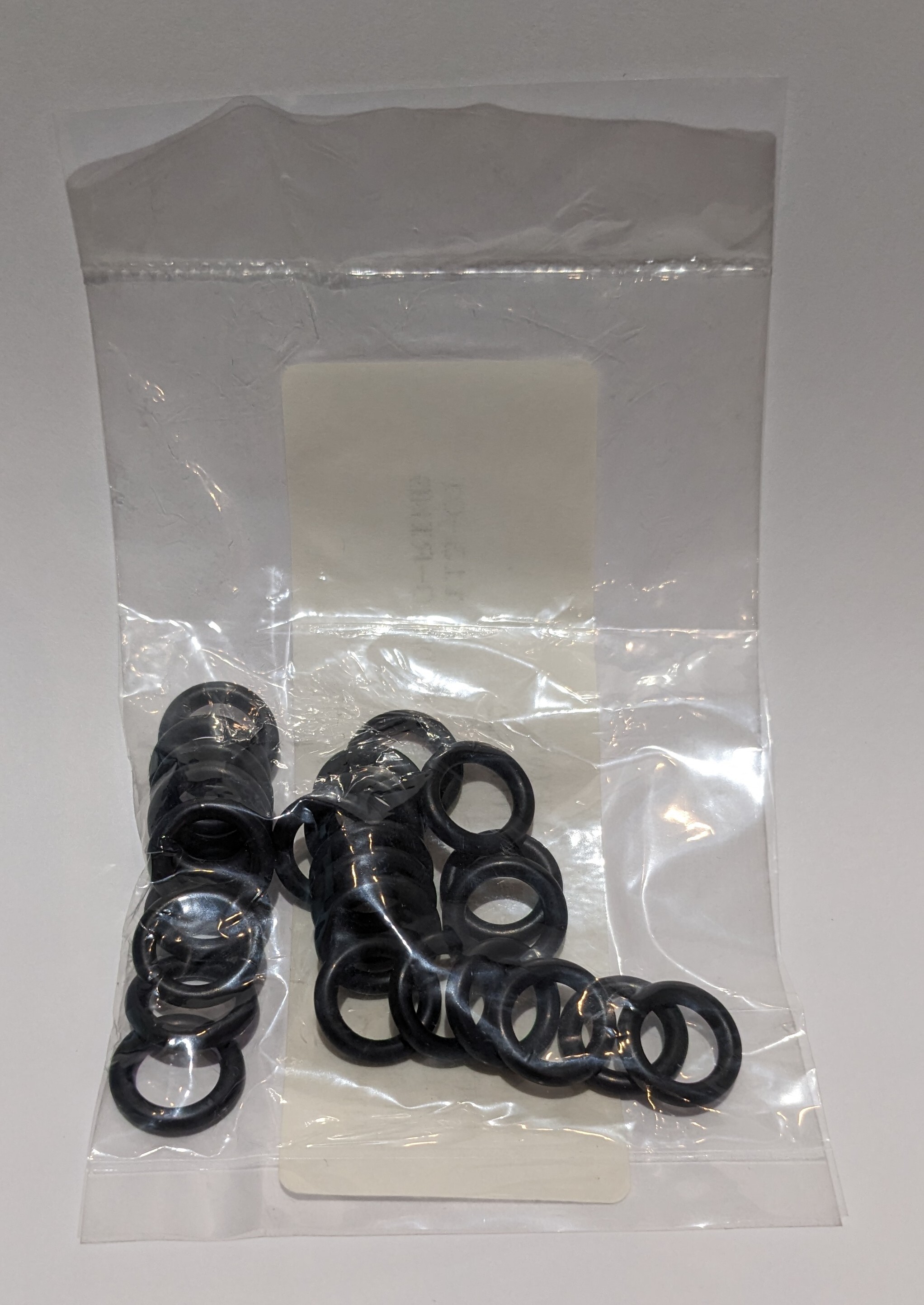
This box includes a bunch of replacement O-rings for the John Guest fittings in my RO system. If you've ever tried to buy replacement O-rings you will have been frustrated by the fact that it's very difficult to figure out what kind of O-rings they are and that they are available in very small packages for a ridiculously high price.
They are EDPM Dash 110 O-rings (McMaster-Carr catalog number 9561K41 .) $1.71 for 25 pcs.
- Vacuum transducer calibration rig.
This is the setup I used to calibrate the vacuum sensor. The vacuum line connects on the right. The right T is the vacuum sensor. The left T is a vacuum gauge. The ball valve allows me to easily release the vacuum.
I use the vacuum transducers to monitor the vacuum level on the pump side and the collection (tree) side of the vacuum releaser.
- Oil tank evaporator build (Part 2).
Continued from Part 1.
[!image](https://i.imgur.com/miD8asK.jpg)
Once we were happy with the setup Lulu started welding. Here she's welding the cross bars into place.
[!image](https://i.imgur.com/wCQKxS7.jpg)
We've taken a bit of a leap forward at this point. The floor of the fire box is welded in, we've installed the back of the fire box, and the cross bars for the rear baffle are welded into place.
In the next version of this evaporator I plan to bring an air feed in under the baffle at the back so that I can push air in under the first grate. This rear wall of the fire box is solid.
[!image](https://i.imgur.com/oazQXV7.jpg)
In this photo we've added the framing for the fire bricks on the back wall of the fire box and are test fitting couple of fire bricks, one at each end.
[!image](https://i.imgur.com/JzDZU7V.jpg)
We used a big piece of cardboard to make a template for the left half of the rear baffle. The oil tank has lots of indents and curves to work around.
[!image](https://i.imgur.com/n0mMXME.jpg)
We traced the cardboard template onto a piece of steel sheet and cut it out. The fit wasn't bad but there was going to be some gap filling to do.
I think that in retrospect I would have used treaded rod and a turnbuckle to close some of this gap for welding. I'll do that next time and take pictures.
[!image](https://i.imgur.com/udcxqob.jpg)
We made the sides of the baffles out of multiple pieces of sheet because that's what we could cut out of the other tank. We used the same process here, drilling holes so that we could weld the sheet to the cross bars.
[!image](https://i.imgur.com/8zbXt5K.jpg)
There was lots of welding and lots of grinding to do to get the rear baffle installed but we got it done.
[!image](https://i.imgur.com/3Pqvb25.jpg)
These two cross bars behind the top frame cross bar we saw earlier will support the chimney connector. Note the circular cutouts for the chimney ring.
[!image](https://i.imgur.com/HdP3m4v.jpg)
The hole in the rear deck lines up with the circular cutouts in the cross bars.
[!image](https://i.imgur.com/rB4l5Qm.jpg)
The chimney ring sits above the hole on the rear deck and we welded everything together.
[!image](https://i.imgur.com/nsoDuyW.jpg)
We careful when you're using zip cut disks. They have no respect for work gloves or fingers.
[!image](https://i.imgur.com/5KJISzJ.jpg)
I spent too much time producing this paper template for the point where the leg meets the tank. We wrapped the paper around the tube, clamped the tube in place, then scribed the connection with a block of wood and a Sharpie. I then spent time working with scissors to improve the fit.
Next time I do this I will build the jig that you see in the next photo and scribe the connection with the leg clamped in the jig.
[!image](https://i.imgur.com/p6zMbqq.jpg)
This large rectangular jig sits on the tank and holds the legs in place for welding. We were able to tap the jig to adjust it to make sure that it was level in relation to the tank and that the legs were therefore plumb.
[!image](https://i.imgur.com/WZQkrpU.jpg)
We marked the tank and did some weld prep.
[!image](https://i.imgur.com/bmf3UVZ.jpg)
Next, we tacked the legs and the long axis gussets. The legs on the old evaporator were flimsy. These ones would not be.
[!image](https://i.imgur.com/bmf3UVZ.jpg)
We then removed the jig, used carboard to design and cut the short axis gussets, tacked them in place, and welded the leg and gussets.
[!image](https://i.imgur.com/s99BGO1.jpg)
Now we could finally get it up on its feet. This is, I believe, the greatest improvement over the old evaporator. Using the screw type scaffold jack feet allows me to level the evaporator on uneven ground or an uneven floor. Even in my new sugar shack the ground moves a bit in the spring. Being able to kick the handles and bring it back into level easily is amazing. I had to shorten the legs a bit but that was easily done with a cutting disk on the grinder as they were hollow. Solid ones would be harder to cut but the hollow ones work fine for this application.
You can see in this photo that we have started to tack together the fire grate. It's made of 1 1/2" x 1/4" bar and 2" x 2" x 1/4" angle.
[!image](https://i.imgur.com/ktyGJAx.jpg)
A closer look at the tacked grate.
In the next version I will weld bar onto the open side of the angle to add additional strength. With differential heading from the fire the grate warped.
[!image](https://i.imgur.com/VG9PqNs.jpg)
The door is a frame of 1" x 1/2" steel channel with a field of steel sheet. The hinges are trimmed down and welded to the door frame and the frame of the door.
[!image](https://i.imgur.com/liMgvjx.jpg)
I glued wood stove gasket into the channel frame on the door to keep the smoke in. The chimney drafts enough air that smoke doesn't home out the vent holes.
[!image](https://i.imgur.com/HARzGHh.jpg)
We built the door handle and closure out of some scraps of steel that I had in my scrap bucket.
This was a great build and Lulu and I had a lot of fun. There are LOTS more photos that I didn't include here. If you're interested in any specific aspect of this build or have any questions please feel free to ask or comment.
- Oil tank evaporator build (Part 1).
This is going to be a long post. I will likely have to break it up into parts. So this is Part 1.
In the late winter of 2019 my hand, Lulu, and I built a new oil tank evaporator.
(You can click on the images to see higher resolution versions.)
This is my original evaporator. My wife bought it from a local guy about four years before. It worked ok but I wanted to make improvements.
[!image](https://i.imgur.com/FOEg9SD.jpg)
Note that the door doesn't fit well and the legs are the original oil tank legs which are intended to sit on a concrete floor and not be moved. The body of the evaporator is completely open so I had to pile concrete blocks and piece of steel in there to deflect the heat toward the bottom of the pan.
[!image](https://i.imgur.com/k5BTEGm.jpg)
The pan was steel, folded and soldered and it leaked and was hard to get clean. The hardware was mostly brass and was tenuously connected to the pan.
[!image](https://i.imgur.com/AGSUTaR.jpg)
Lulu (L) and I (R) set out to make improvements.
[!image](https://i.imgur.com/US2tdJ3.jpg)
This is the oil tank that will become the body of our evaporator (and later the body of the evaporator and replaced and improved on this one.
PLEASE NOTE: Cutting an oil tank or any container which has contained flammable liquid will KILL YOU. This is NOT something that you should try unless you know exactly what you're doing. Seriously, it will explode and it will fuck you up.
[!image](https://i.imgur.com/kTeUY3r.jpg)
We used welding magnets and aluminum angle to draw a line around the middle of the tank. I think cut the tank in half. (Read the warning above. I'm not going to tell you how I did this. If you don't know how to do it safely get help or ask someone who does know how to do it safely to do it for you.)
[!image](https://i.imgur.com/3IqqSIh.jpg)
It was getting late when we finished cutting the tank in half so this photo is a bit dark.
[!image](https://i.imgur.com/aMIC41T.jpg)
We built a frame out of 2" x 2" x 1/8" steel angle. Here we have the long sides clamped to the top of the tank, squeezing the sides straight so that we can measure the length of the required short pieces. The sides of the tank bow out once it is cut in half. You don't want to squeeze it so hard that the side bows in. Just look at where the angle hits the tank and make sure that it's touching the tank along it's full length.
[!image](https://i.imgur.com/6DpTece.jpg)
We cut the long and short pieces on the dry cut saw then prepared the corners. We used right angle welding corner clamps to hold them in alignment while we welded them.
[!image](https://i.imgur.com/AX4Jj90.jpg)
Once the corners were welded we did some grinding. So much grinding. When you're an amateur welder the angle grinder is your friend. My hand had never welded before coming to stay with us so she did a lot of learning on this project. I let her do a lot of the welding then came along behind her and did some grinding and touch ups where necessary.
[!image](https://i.imgur.com/0ERWkei.jpg)
We laid out for, measured, and cut a 2" x 1/2" flat bar door frame.
[!image](https://i.imgur.com/Mkjej1R.jpg)
Next, we cut and welded on the first of three cross bars in the top frame. This one is upside down compared to the other two. This one is the back edge of the pan. Behind it is the read deck where the chimney connector will be.
[!image](https://i.imgur.com/7YEM6a2.jpg)
This little Cub Cadet/Yanmar tractor acted as our welding table for the project. Here you can see the top frame with the rear cross bar. Note also the interrupted weld around the outside bottom of the top frame. The inside of the top frame is continuously welded.
We didn't install the other two cross bars at this point because they would have been in our way as we did the interior welding.
[!image](https://i.imgur.com/7YEM6a2.jpg)
We marked and cut the door opening in the end of the tank.
[!image](https://i.imgur.com/hClBSq7.jpg)
Then we welded in the door frame. The welds are ugly but we're amateurs.
[!image](https://i.imgur.com/PmHXsSs.jpg)
In this photo we're working on how we're going to attach the half fire bricks to the evaporator. We decided on some 1 1/2" x 1 1/2" x 1/8" angle at the top and bottom with two pieces of the same angle welded back to back with 1/4"-20 studs to attach it to the wall to retain the bricks where they meet.
[!image](https://i.imgur.com/NWmaacV.jpg)
This was the retainer bar that we built. We slipped the fire bricks into the upper and lower angles then slipped this bar in between the two courses of bricks and bolted it to the side the tank.
[!image](https://i.imgur.com/xCbpTd8.jpg)
In this photo we're doing a fit up to see where the holes need to be drilled for the retaining bar and where the lower angle needs to be welded on.
[!image](https://i.imgur.com/c309zg1.jpg)
In this photo we have the lower angle welded in and are just testing to see how the whole setup works. It works well.
[!image](https://i.imgur.com/8RQKR8u.jpg)
Next, we started to build the back and bottom frames of the fire box. The plan was to build a baffle at the back of the first box to direct the heat up and a baffle across the back of the tank to hold the heat against the bottom of the pan.
[!image](https://i.imgur.com/arXOm9C.jpg)
We cut these three pieces of angle to set the floor even with the bottom of the door to make it easy to drag out the coals and ashes when the boil was done.
This is one of the things that I am going to fix in the next evaporator build. I should have set the floor down the thickness of a half fire brick so that the floor of the evaporator was protected. The heat of the fire built directly on the floor of the fire box caused it to warp.
[!image](https://i.imgur.com/1CfaMSh.jpg)
Most of the flat steel you see in this build came from another oil tank that we cut up as we needed pieces.
Please reread the warning about cutting oil tanks at the beginning of this post.
[!image](https://i.imgur.com/wbJVNLc.jpg)
Here you can see the piece we cut out of the tank above to use as the floor of the first box. We did some cutting and grinding to get a decent fit.
[!image](https://i.imgur.com/JGKpQqS.jpg)
We drilled a series of holes to line up with the middles of the cross bars so we could weld the sheet onto the cross bars.
[!image](https://i.imgur.com/yUK63Zj.jpg)
Everything was dry fit together so that we could make adjustments before we started welding. We ground back the plate a bit at the ends of the cross bars so we could wend the cross bars to the tank well.
Continued in Part 2.
- Full System Tour of my Machine Room (YouTube Video in Comments)
YouTube Video Full System Tour of my Machine Room
This is a video that I made this spring to explain what's in my machine room and what it does as well as the supporting development and operations hardware in my office.
- February 2018 - My first homemade RO system.
Like most of the things I build this was put together from parts I bought on Ebay, at Lowe's and my local Home Hardware. It used 100 GPD membranes and a small booster pump. It chugged away but we quickly outgrew it.
- February 2018 - The first vacuum releaser I ever built.
I built this releaser from PVC pipe that I bought at Lowe's in Ogdensburg, NY, check valves and solenoids that I bought on Ebay, and fence T-bars that I bought at TSC. The controller was an Arduino Nano in the grey box on the side of the releaser. This one was vertical and sat on top of the IBC draining into the port on the top. It worked quite well and didn't cost a lot to build. I can't remember how much it released per dump but it was under 4 L.
- March 2020 - The first time I used the new machine.
In 2020 I a hand and I built this insulated box so hold the vacuum pump, RO pumps, vacuum releaser, and RO. This prevented them from freezing overnight and eliminated the necessity to carry them in every night and back out every morning. The vacuum releaser is the two white circles on the right. The little heater bottom right stayed on overnight.
The only problem with this system was that my main storage, a 1,000 L IBC, was outside and the plumbing and valves froze up. It was a big improvement but it left a lot of room for improvement.
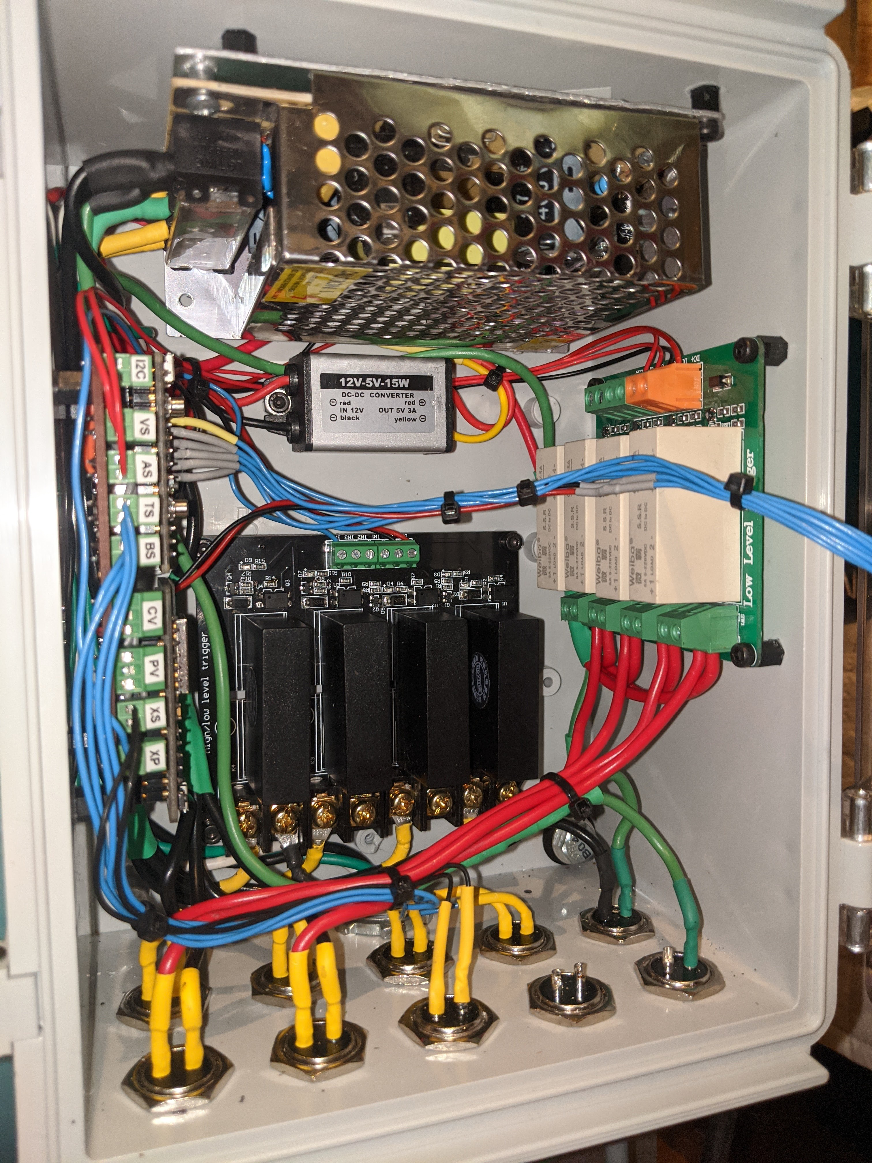
- This is an Arduino.
This is the machine that runs my maple syrup machine room. The PLC (the large grey box on the left in the second section from the top) runs a MEGA2560 Pro Mini with an ESP32 as a WiFi modem. There are more than 4,000 lines of BascomAVR running on the MEGA2560 and around 800 lines of Sketch on the ESP32.
The top section is power distribution. The middle section is supposed to be PLC only but my 24V power supply and distribution leaked into the right hand end opposite the PLC. The bottom three sections from left to right are analog input, digital input, and digital output.
This thing runs a vacuum pump (a MasterCool 90066A), a transfer pump (a small Iwaki), an RO pump, and two solenoid valves (to be replaced with motorized ball valves this summer.) It takes inputs from a bunch of float switches, two vacuum transducers, a pressure transducer, three high precision digital thermometers, and two last time of flight sensors. This thing runs the entire process from the trees through collection and storage through the RO into secondary storage and out a tap to be boiled in the evaporator.
The PLC uses a pair of custom boards that I designed to fit in the BUD case they're installed in. I'll post pictures of the inside shortly.